
The previous article introduced the architecture of Neutron. Over the next few days, I will introduce the architecture and traffic flow when Neutron uses Linux Bridge and OVS plug-ins. In this first post, I will start by introducing Linux Bridge with Provider Networks.
Contents
Linux Bridge: Provider Networks
The Provider network architecture example uses VLAN (802.1q) tagging to provide L2 connectivity between instances and the physical network infrastructure. It supports one non-tagged (flat) network and up to 4,095 tagged (VLAN) networks. The actual number of VLAN networks depends on the physical network infrastructure.
Architecture
The diagram above provides an overview of the entire architecture under Linux Bridge – Provider Networks. You can see which components run on the controller node and which run on the compute node.
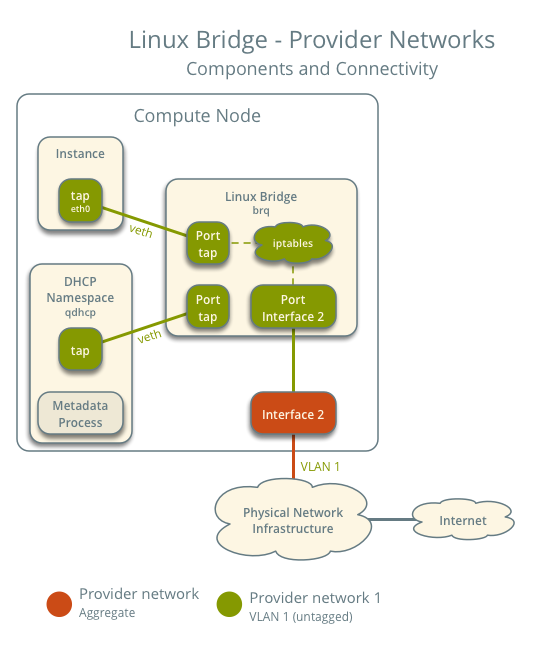
This diagram illustrates how components within a compute node are interconnected under a single provider network. In this example, the Instance and the DHCP agent are on the same node; however, in practice, the DHCP agent might reside on a different compute node.
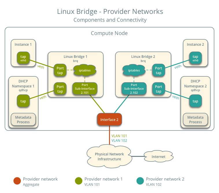
In scenarios with multiple Provider networks, each provider network corresponds to a Linux Bridge on every compute node and is isolated using VLANs. Instances on the compute host connect their network interfaces to the Linux bridge corresponding to their respective network.
Traffic Flow
This section introduces how packets actually flow through the architecture under various scenarios.
Architecture Configuration
Below is our envisioned architecture, featuring two provider networks isolated via VLANs, each with one instance running on it.
- Provider Network 1 (VLAN)
- VLAN ID 101 (Tagged)
- IP address range 203.0.113.0/24
- Gateway (on the physical network)
- IP 203.0.113.1
- Provider Network 2 (VLAN)
- VLAN ID 102 (tagged)
- IP address range 192.0.2.0/24
- Gateway
- IP 192.0.2.1
- Instance 1
- IP 203.0.113.101
- Instance 2
- IP 192.0.2.101
North-South Traffic
- Instance on compute node 1
- Instance sends packets to the external network
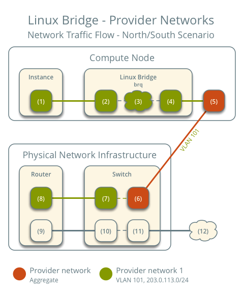
- The instance's network interface (1) sends packets to the instance port on the provider bridge via a veth pair (2)
- On the provider bridge, iptables (3) handles firewall and connection tracking
- The VLAN sub-interface port (4) on the provider bridge sends packets to the physical network interface (5)
- The physical network interface adds VLAN tag 101 and sends the packet to the switch (6) in the physical network infrastructure
The subsequent part is consistent with general networking principles: packets are sent to the router and then forwarded out. The return path for packets follows the exact reverse process.
East-West Traffic 1: Instances on the same network
- Instance 1 on compute node 1
- Instance 2 on compute node 2
- Instance 1 sends packets to Instance 2
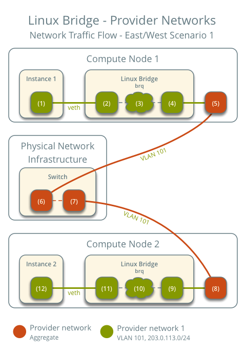
The preceding steps are exactly the same.
- The instance's network interface (1) sends packets to the instance port on the provider bridge via a veth pair (2)
- On the provider bridge, iptables (3) handles firewall and connection tracking
- The VLAN sub-interface port (4) on the provider bridge sends packets to the physical network interface (5)
- The physical network interface adds VLAN tag 101 and sends the packet to the switch (6) in the physical network infrastructure
Within the physical network infrastructure:
- The switch sends packets from compute node 1 to compute node 2
After the packet reaches compute node 2:
- The physical network interface (8) removes VLAN tag 101 and sends the packet to the VLAN sub-interface port (9) on the provider bridge
- On the provider bridge, iptables (10) handles firewall and connection tracking
- The instance port (11) on the provider bridge sends packets to the network interface (12) of instance 2 via a veth pair
East-West Traffic 2: Instances on different networks
- Instance 1 is on compute node 1 and uses provider network 1
- Instance 2 is on compute node 1 and uses provider network 2
- Instance 1 sends packets to Instance 2
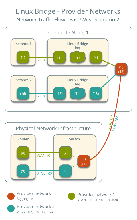
The initial process for sending the packet out is also the same.
- The instance's network interface (1) sends packets to the instance port on the provider bridge via a veth pair (2)
- On the provider bridge, iptables (3) handles firewall and connection tracking
- The VLAN sub-interface port (4) on the provider bridge sends packets to the physical network interface (5)
- The physical network interface adds VLAN tag 101 and sends the packet to the switch (6) in the physical network infrastructure
Within the physical network infrastructure:
- The switch removes the VLAN tag 101 from the packet and sends it to the router (7).
- The router routes the packet from provider network 1 (8) to provider network 2 (9).
- The router sends the packet to the switch (10).
- The switch removes the VLAN tag 102 from the packet and sends it to compute node 1 (11).
Back on compute node 1:
- The physical network interface (12) removes the VLAN tag 102 and sends it to the VLAN sub-interface port (13) on the provider bridge.
- On the provider bridge, iptables (14) handles the firewall and connection tracking.
- The instance port (15) on the provider bridge sends the packet to the network interface of instance 2 (16) via a veth pair.
The above covers the packet traffic flow for Linux Bridge Provider Networks under various scenarios.
Summary
This article introduces the architecture and packet flow under Linux Bridge – Provider Network. Understanding how network packets flow will give you a better conceptual grasp when debugging connectivity issues. The next article will introduce the architecture and packet flow using Linux Bridge – self-service network.
Copyright Notice: All articles on this blog are licensed under CC BY-NC-SA 4.0 unless otherwise specified.

