
The previous article introduced the architecture and packet flow of Linux Bridge with Provider Network; today's post will introduce Linux Bridge with self-service networks.
Contents
Linux Bridge: Self-Service Networks
Self-service networks provide users with an almost unlimited number of virtual networks. Although Neutron supports VLAN self-service networks, this example uses VXLAN self-service networks.
Architecture
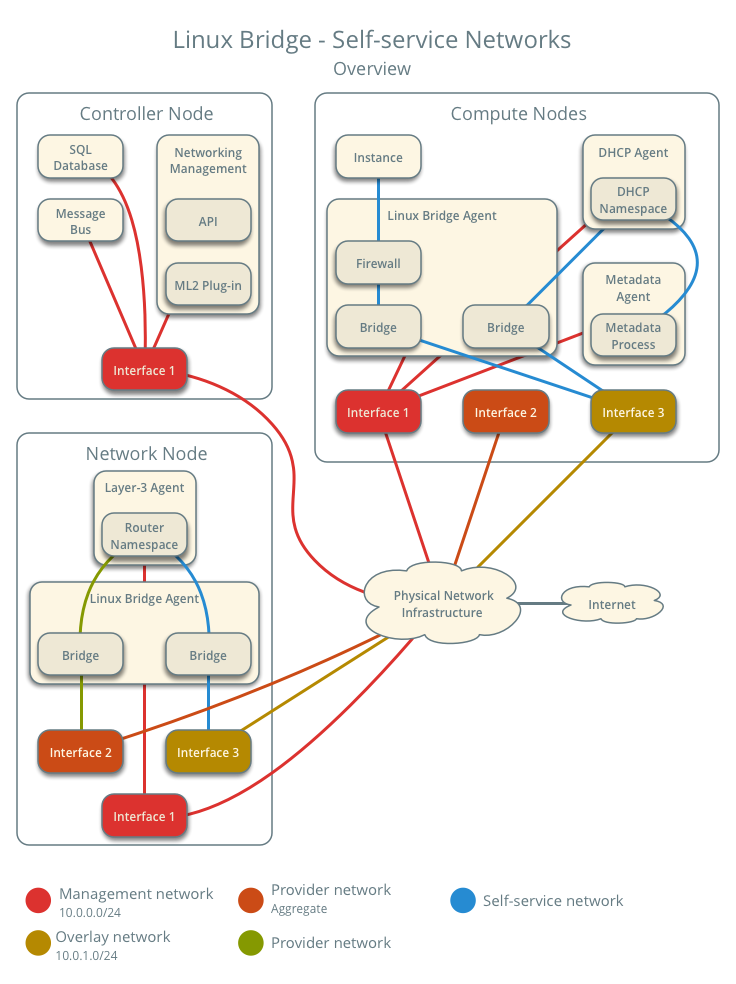
The diagram above provides an overview of the entire Linux Bridge – Self-service networks architecture. You can see which components run on the controller node, the compute node, and the network node.
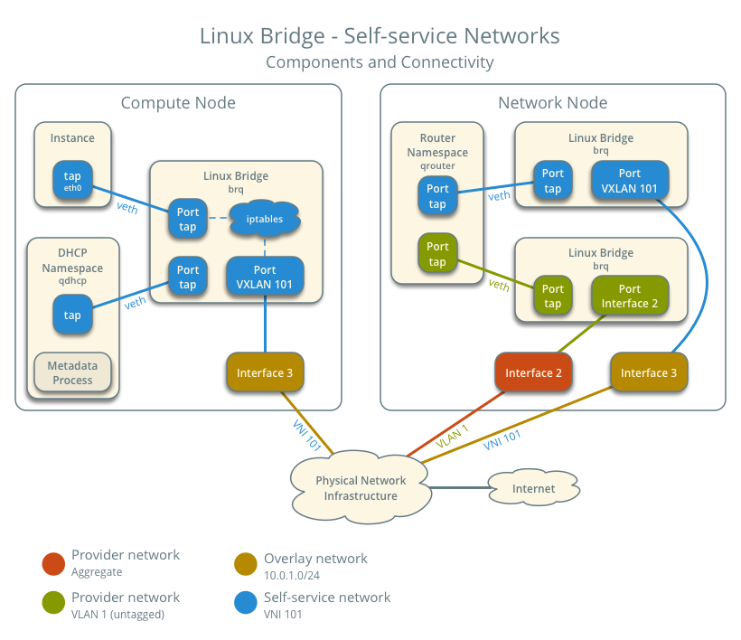
This diagram illustrates how the components used in self-service networks are interconnected under a single provider network. In this example, the Instance and the DHCP agent are on the same machine, but in practice, the DHCP agent might reside on a different compute node.
Traffic Flow
This section introduces how packets actually flow through the architecture under various scenarios.
Architecture Configuration
Below is our envisioned architecture, featuring two self-service networks isolated via VXLAN, each with one instance.
- Provider Network 1 (VLAN)
- VLAN ID 101 (Tagged)
- Self-Service Network 1 (VXLAN)
- VXLAN ID (VNI) 101
- Self-service network 2 (VXLAN)
- VXLAN ID (VNI) 102
- Self-service router
- Gateway on the provider network
- Interface on self-service network 1
- Interface on self-service network 2
- Instance 1
- Instance 2
North-South Traffic 1: Instance with Fixed IP
For instances with fixed IPv4 addresses, the network node performs SNAT on North-South traffic traveling from self-service networks to external networks like the Internet. For instances with fixed IPv6 addresses, the network node sends packets to the external network via regular routing.
- Instance on compute node 1 using self-service network 1
- Instance sends packets to the external network
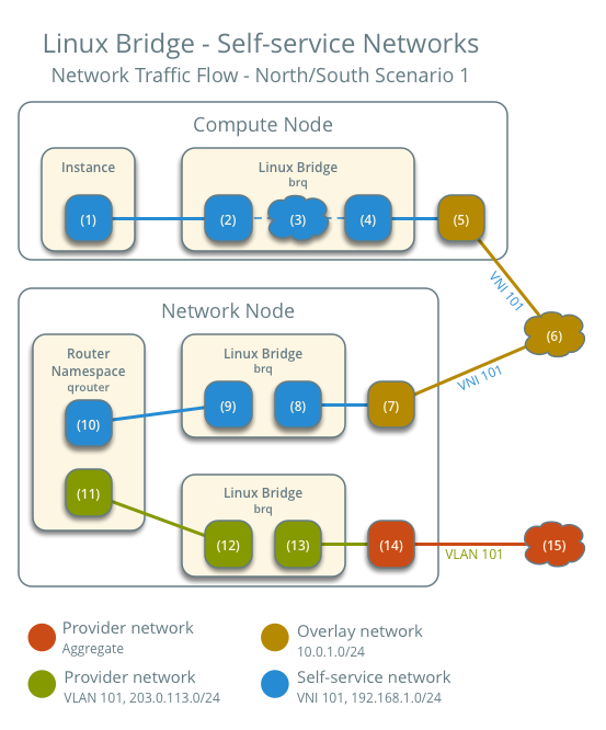
- The instance's network interface (1) sends packets to the instance port on the self-service bridge via a veth pair (2).
- On the self-service bridge, iptables (3) handles firewall rules and connection tracking.
- The VXLAN interface (4) on the self-service bridge encapsulates the packet into VNI 101.
- The physical network interface (5) corresponding to the VXLAN interface sends the packet to the network node (6) via the overlay network.
After the packet reaches the network node:
- The physical network interface (7) corresponding to the VXLAN interface sends the packet to the VXLAN interface (8), which decapsulates the VXLAN packet.
- The router's self-service bridge interface (9) sends the packet to the self-service network interface (10) within the self-service router namespace.
- For IPv4, the router uses SNAT to change the source IP to the router's IP and then sends the packet to the gateway via the gateway interface (11) on the provider network.
- For IPv6, the router sends the packet to the next-hop IP address, typically the provider network gateway, via the gateway interface (11) on the provider network.
- The router sends the packet to the router's provider bridge interface (12).
- The VLAN sub-interface port (13) on the provider bridge sends the packet to the provider physical network interface (14).
- The provider physical network interface (14) adds VLAN tag 101 to the packet and sends it to the physical network infrastructure (15).
The subsequent part is the same as general networking knowledge: the packet is sent to the router within the physical network and then transmitted out. The return path for the packet follows the exact reverse process.
North-South Traffic 2: Instance with Floating IP
For instances with fixed IPv4 addresses, the network node performs SNAT on North-South traffic from self-service networks to external networks like the Internet and performs DNAT on traffic returning from the external network. Floating IPs do not apply to IPv6.
Since the packet flow from the instance to the external network is the same as in Example 1, I won't go into detail here. The only difference is that the SNAT IP is replaced by the floating IP instead of the router's IP. This section will introduce the traffic returning from the external network.
- Instance on compute node 1 using self-service network 1
- The external network sends packets to the instance.
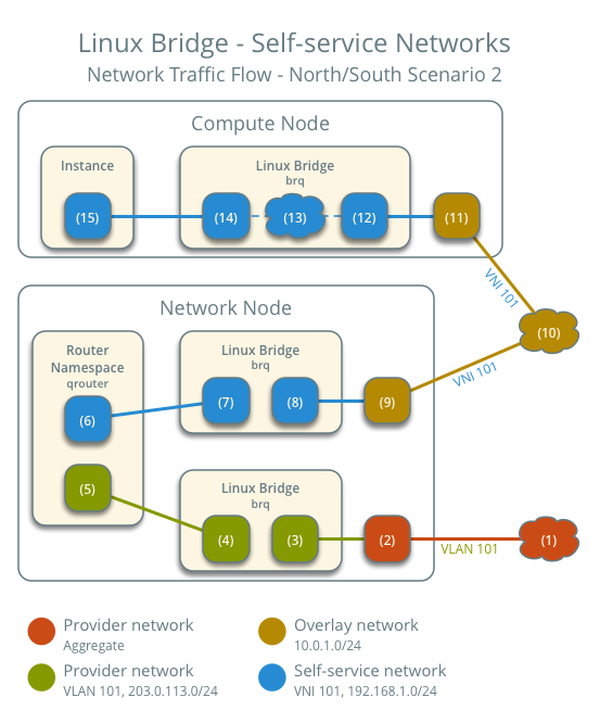
After the external network packet reaches the network node:
- Physical network infrastructure (1) sends packets to the provider physical network interface (2).
- The provider physical network interface (2) removes the VLAN tag 101 and sends the packet to the VLAN sub-interface port (3) on the provider bridge.
- The provider bridge (4) sends the packet to the provider gateway interface (5) of the self-service router.
- In the case of IPv4, the router uses DNAT to change the destination IP to the instance's IP and then sends the packet to the self-service network via the self-service interface (6).
- In the case of IPv6, the router sends the packet to the next-hop IP address, which is typically the gateway of the self-service network, also via the self-service interface (6).
- The router sends the packet to the self-service bridge router interface (7).
- The self-service bridge sends the packet to the VXLAN interface (8) and encapsulates it within VNI 101.
- The physical network interface (9) sends the VXLAN packet to the compute node via the overlay network (10).
After the packet reaches the compute node:
- The physical network interface (11) sends the packet to the VXLAN interface (12) and decapsulates VNI 101.
- On the self-service bridge, iptables (13) handles firewalling and connection tracking.
- The instance port (14) on the self-service bridge sends the packet to the instance's network interface (15) via a veth pair.
The above describes the return packet flow when using a Floating IP.
East-West Traffic 1: Instances on the same network
- Instance 1 is located on compute node 1 and uses self-service network 1.
- Instance 2 is located on compute node 2 and uses self-service network 1.
- Instance 1 sends packets to Instance 2
The preceding steps are exactly the same.
- The instance's network interface (1) sends packets to the instance port on the self-service bridge via a veth pair (2).
- On the self-service bridge, iptables (3) handles firewall rules and connection tracking.
- The VXLAN interface (4) on the self-service bridge encapsulates the packet into VNI 101.
- The physical network interface (5) corresponding to the VXLAN interface sends the packet to compute node 2 (6) via the overlay network.
After the packet reaches compute node 2:
- The physical network interface (7) forwards the packet to the VXLAN interface (8) and decapsulates VNI 101.
- On the self-service bridge, iptables (9) handles firewall rules and connection tracking.
- The instance port (10) on the self-service bridge forwards the packet to the instance's network interface (11) via a veth pair.
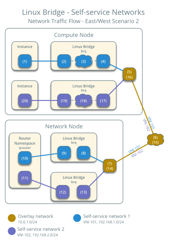
East-West Traffic 2: Instances on different networks
- Instance 1 is on compute node 1 and uses self-service network 1
- Instance 2 is on compute node 1 and uses self-service network 2
- Instance 1 sends packets to Instance 2
The initial process for sending the packet out is also the same.
- The instance's network interface (1) sends packets to the instance port on the self-service bridge via a veth pair (2).
- On the self-service bridge, iptables (3) handles firewall rules and connection tracking.
- The VXLAN interface (4) on the self-service bridge encapsulates the packet into VNI 101.
- The physical network interface (5) corresponding to the VXLAN interface sends the packet to compute node 2 (6) via the overlay network.
After the packet reaches the network node:
- The physical network interface (7) corresponding to the VXLAN interface sends the packet to the VXLAN interface (8), which decapsulates the VXLAN packet.
- The router's self-service bridge interface (9) sends the packet to the self-service network 1 interface (10) within the self-service router namespace.
- The router sends the packet through the self-service network 2 interface (11) to the self-service network gateway.
- The router sends the packet to the router's self-service network 2 bridge interface (12).
- Self-service network 2 bridge 將封包包在 VNI 102 並且送往 VXLAN 介面
- VXLAN 介面對應的實體網路介面 (14) 將封包透過 overlay network 送往 compute node 1
Back on compute node 1:
- 實體網路介面 (16) 將封包送往 VXLAN 介面 (17) 並且解開 VNI 102
- 在 self-service bridge 上 iptables (18) 會處理防火牆跟 connection tracking
- self-service bridge 的 instance port (19) 透過 veth pair 將封包送往 Instance 的網路介面 (20)
The above covers the packet flow for Linux Bridge self-service networks under various scenarios.
Summary
This article introduces the architecture and packet flow under Linux Bridge Self-Service Networks. Similarly, understanding how network packets flow will provide you with a better conceptual foundation when debugging network connectivity issues. The next article will introduce the architecture and packet flow using Open vSwitch: Provider networks.
Copyright Notice: All articles on this blog are licensed under CC BY-NC-SA 4.0 unless otherwise specified.

